
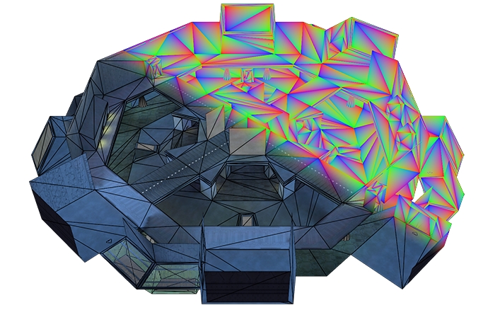
A render of Derelict from Bungie’s Halo: Combat Evolved. Rendered using an experimental Vulkan-renderer I am making utilizing
GL_EXT_fragment_shader_barycentricfor rendering high-quality wireframes.
GL_EXT_fragment_shader_barycentric is a more vendor-neutral version of both Nvidia’s GL_NV_fragment_shader_barycentric extension, and AMD’s GL_AMD_shader_explicit_vertex_parameter extension which allows fragment shaders to directly access the barycentric weights of the current sample.
Now that this feature is no longer exclusive to a particular vendor’s hardware, I figure now is a good time to finally write a cool use-case for this extension. Wireframe rendering!
Barycentric weights, in the 2D or 3D triangle-case, are the contribution factors used when interpolating vertex-attributes across the surface of a triangle. When you attach data such as vertex colors or directional normals to the output of a vertex shader, barycentric coordinates are what the GPU use to linearly interpolate these attributes across each fragment when rasterizing.
There are many great explanations of Barycentric Coordinates being used in relation to computer graphics. I’ll link some here:
- Fragment Interpolation - Brendan Galea
- barycentric hecking interpolation!! - Freya Holmér
- Vertex Attributes Triangle Interpolation - Jamie King
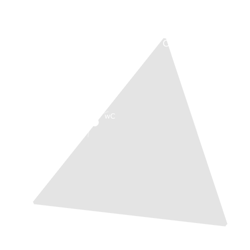
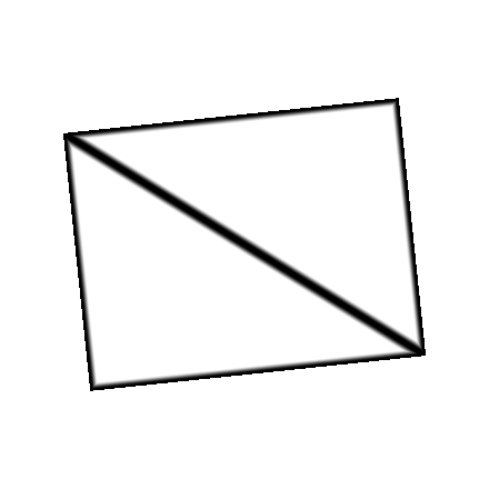
If you have vertices $A$, $B$, and $C$, you can think of the barycentric coordinates ${w_A,w_B,w_C}$ as a particular mixture of these three points that corresponds to another arbitrary point within the triangle $\triangle{ABC}$.
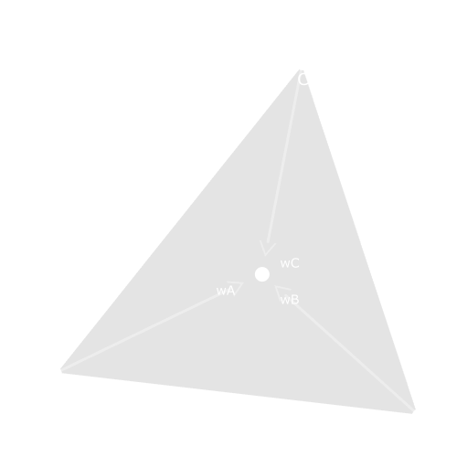 |
The very center of the triangle would be an even mixture of $\frac{1}{3}A + \frac{1}{3}B + \frac{1}{3}C$. |
 |
The middle point of edge $\overline{\rm AB}$ would be $\frac{1}{2}A + \frac{1}{2}B + 0C$. |
 |
The middle point of edge $\overline{\rm AC}$ would be $\frac{1}{2}A + 0B + \frac{1}{2}C$. |
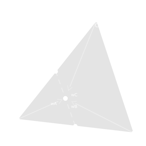 |
The middle point between the middle-points of edges $\overline{\rm AB}$ and $\overline{\rm AC}$ would be $\frac{1}{2}A + \frac{1}{4}B + \frac{1}{4}C$. |
The general-case for barycentric coordinates but for any convex shape is a convex combination.
When GL_EXT_fragment_shader_barycentric is included within your GLSL fragment shader, you now have access to the global variables in vec3 gl_BaryCoordEXT and in vec3 gl_BaryCoordNoPerspEXT.
gl_BaryCoordEXT are the perspective-correct barycentric weights(${w_A,w_B,w_C}$) for each vertex for the triangle being rasterized.
gl_BaryCoordNoPerspEXT is the same as gl_BaryCoordEXT but with no perspective-correction should you ever need it.
The extension also allows you to manually access per-vertex attributes within a fragment shader with a
pervertexEXTinput-block to interpolate vertex-attributes yourself but we’re just interested in the barycentric coordinates right now.
#extension GL_EXT_fragment_shader_barycentric  : require

layout( location = 0 ) out f32vec4 Attachment0;

void main()
{
	Attachment0 = vec4(gl_BaryCoordEXT, 1.0);
}
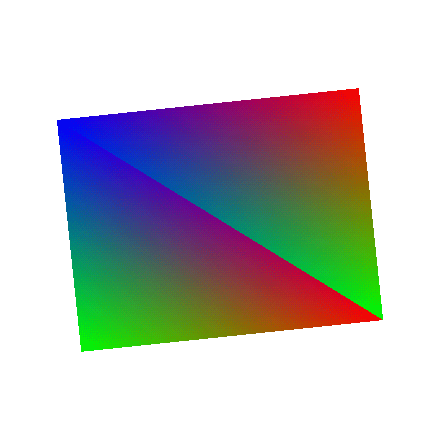
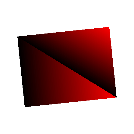
| Red | Green | Blue |
|---|---|---|
 |
 |
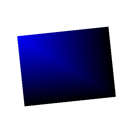 |
The red channel encodes how much of vertex-$A$’s attributes factor into the fragment. The same goes for the blue channel for vertex-$B$, and the green channel for vertex-$C$.
An interesting property of these barycentric coordinates is that as fragments approach an edge, the weight of the vertex opposite of that edge approaches and eventually equals zero.
Another way to interpret this property is that each of three weights can be thought of as a “distance” to edge $\overline{\rm BC}$, $\overline{\rm AC}$, and $\overline{\rm AB}$ on the triangle $\triangle{ABC}$.
You can sort of think of this as a sort of distance field. If you get the minimum value of the three barycentric coordinates, then you will get the distance to the closest edge:
#extension GL_EXT_fragment_shader_barycentric  : require

layout( location = 0 ) out f32vec4 Attachment0;

void main()
{
	const vec3 BaryCoord = gl_BaryCoordEXT;
	const float ClosestEdge = min(BaryCoord.x, min(BaryCoord.y, BaryCoord.z));

	Attachment0 = vec4(ClosestEdge.xxx, 1.0);
}
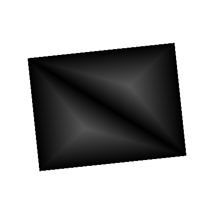
Note that the largest distance, at the very center of the triangles, is $\frac{1}{3}$ since the farthest a fragment can possibly be from any edge is $\frac{1}{3}$ before the fragment is now closer to another edge.
With a distance-field such as this, you can remap these distance values to a particular thickness value and get wireframes!
Here I use smoothstep as a threshold-function of sorts to create a smooth-ish border from distance 0.0 to distance 0.01:
#extension GL_EXT_fragment_shader_barycentric  : require

layout( location = 0 ) out f32vec4 Attachment0;

void main()
{
	const vec3 BaryCoord = gl_BaryCoordEXT;
	const float ClosestEdge = min(BaryCoord.x, min(BaryCoord.y, BaryCoord.z));

	// Remap the input values such that 0.0 maps to 0.0 and 0.01 maps to 1.0
	// while also smoothly interpolating the values between 0.0 and 0.01.
	// Any values outside of this range will just clamp to 0.0 or 1.0
	const float Wireframe = smoothstep(0, 0.01, ClosestEdge);
	// You could just as easily use an "InverseLerp" function rather tha
	// "smoothstep" here but smoothstep is native to GLSL and provides both an
	// inverse-lerp and a smooth interpolation in one function

	Attachment0 = vec4(Wireframe.xxx, 1.0);
}
This might be a “good enough” first-pass implementation of wireframes, but it is not holding up well in some cases.
Notice the lines begin to get especially aliased and pixelated at more oblique angles such as when the triangles begin to “squish” and thicher as the triangles expand.
Depending on the shape and placement of the triangle on-screen, a thickness of 0.01 in barycentric-coordinate-space could span 1000 pixels, 5 pixels, or even less than the size of a pixel.
You can see the line getting thicker as the triangle gets larger, and thinner as the triangle gets smaller.
This is not a stable unit of measurement!
What needs to be done is to have a thickness-value that maps units-of-pixels to units-of-barycentric-coordinates. That way, a thickness of 1.0 or 5.0 can map to the amount of of barycentric-units that must be traversed to determine if a pixel is on the line, off the line, or somewhere in between.
We need partial-derivatives!
With the GLSL functions dFdx and dFdy, one can determine how much an input value changes across a pixel both vertically and horizontally.
Given any value, it will return the screen space “velocity” of this value based on the neighboring pixels.
With both the change in X and change in Y derivatives, the euclidean distance of these derivatives gives you the total magnitude of change.
Some more info:
- Partial Derivatives (fwidth) - Ronja’s tutorials
- Basics of Partial Derivative Shader Funcs in Unity! DDX, DDY, FWidth ✔️ 2021.1 | Game Dev Tutorial - Ned Makes Games
- fwidth - OpenGL 4 Reference Pages - Khronos Registry
The amount of change in barycentric coordinates from one pixel to another in screen-space is constant across the entire triangle. So the derivative will be same across every fragment of the triangle.
The smoothstep function will remap 0.0 to 0.0 and will map dBaryCoord * Thickness to 1.0.
Any value outside of this range will just clamp to 0.0 or 1.0.
You could also do a more typical inverse-lerp to do the same remapping with
t = clamp((x - edge0) / (edge1 - edge0), 0.0, 1.0);smoothstep does this, but also provides some some additional non-linear smoothing
t * t * (3.0 - 2.0 * t);
void main()
{
	const vec3 BaryCoord  = gl_BaryCoordEXT

	// The horizontal and vertical change in barycentric coordinates
	// in screen-space
	const vec3 dBaryCoordX = dFdx(BaryCoord);
	const vec3 dBaryCoordY = dFdy(BaryCoord);

	// `fwidth` gets the manhattan distance of the barycentric coordinates.
	// What you want instead is the euclidean distance
	const vec3 dBaryCoord  = sqrt(dBaryCoordX*dBaryCoordX + dBaryCoordY*dBaryCoordY);

	const float Thickness = 1.5; // In pixels

	const vec3 Remap = smoothstep(
		vec3(0.0),
		dBaryCoord * Thickness,
		BaryCoord
	);

	// Get the closest edge
	const float Wireframe = min(Remap.x, min(Remap.y, Remap.z));

	Attachment0 = vec4(Wireframe.xxx, 1.0);
}
Now, the wireframes are much more consistent. No matter how small or large or oblique the geometry gets, the lines will always be 1.5-pixels thick. There is one more improvement that can be made. With these derivatives, not only can the thickness of the lines themselves be designated but the “softness” of the line as well.
By setting the lower-bound of this remapping to dBaryCoord * Thickness and the upper-bound to dBaryCoord * (Thickness + Falloff) then Thickness-amount of pixels will always be solidly filled and Falloff-amount of pixels will be dedicated to this [0.0,1.0] transition.
I’ve set the falloff width to 6.0 pixels to exaggerate its effect more.
void main()
{
	const vec3 BaryCoord  = gl_BaryCoordEXT

	// The horizontal and vertical change in barycentric coordinates
	// in screen-space
	const vec3 dBaryCoordX = dFdx(BaryCoord);
	const vec3 dBaryCoordY = dFdy(BaryCoord);

	// `fwidth` gets the manhattan distance of the barycentric coordinates.
	// what you want instead is the euclidean distance
	const vec3 dBaryCoord  = sqrt(dBaryCoordX*dBaryCoordX + dBaryCoordY*dBaryCoordY);

	const float Thickness = 1.5; // In pixels
	const float Falloff = 6.0;   // In pixels

	const vec3 Remap = smoothstep(
		dBaryCoord * Thickness,
		dBaryCoord * (Thickness + Falloff),
		BaryCoord
	);

	// Get the closest edge
	const float Wireframe = min(Remap.x, min(Remap.y, Remap.z));

	Attachment0 = vec4(Wireframe.xxx, 1.0);
}
Not only are these lines higher-quality and more customizable than the usual fixed-function wireframe rendering that your graphics API has, but you also get hidden-line removal!
Try it out sometime!
Here’s something you can just copy-paste:
#extension GL_EXT_fragment_shader_barycentric  : require

float WireFrame(in float Thickness, in float Falloff)
{
	const vec3 BaryCoord = gl_BaryCoordEXT;

	const vec3 dBaryCoordX = dFdxFine(BaryCoord);
	const vec3 dBaryCoordY = dFdyFine(BaryCoord);
	const vec3 dBaryCoord  = sqrt(dBaryCoordX*dBaryCoordX + dBaryCoordY*dBaryCoordY);

	const vec3 dFalloff   = dBaryCoord * Falloff;
	const vec3 dThickness = dBaryCoord * Thickness;

	const vec3 Remap = smoothstep(dThickness, dThickness + dFalloff, BaryCoord);
	const float ClosestEdge = min(min(Remap.x, Remap.y), Remap.z);

	return 1.0 - ClosestEdge;
}
